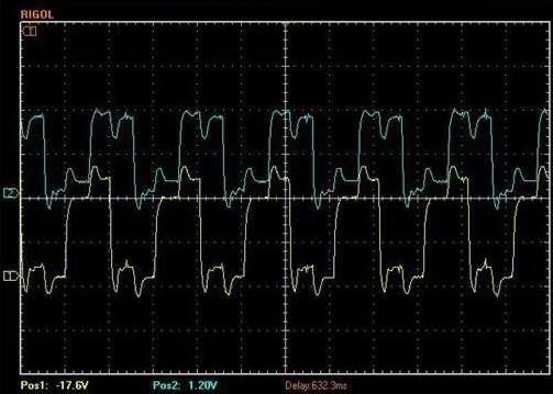
incremental encoderBasic waveform and circuit analysis of
incremental encoderAbsolute encoders are sensors that output in the form of pulses. The outer and middle channels of the code disk of an absolute encoder have the same number of uniformly distributed light-transparent and light-impermeable sectors, but the two sectors are staggered by half a sector from each other. When the code disk rotates, its output signals are the phase A and B pulse signals with a phase difference of 90° and the pulse signal generated by the third code channel with only one light-transparent slit. From the phase relationship between the A, B two output signals can be judged from the direction of rotation (direction). When the code disk is rotating forward, the A-channel pulse waveform is π/2 ahead of the B-channel, and when it is rotating backward, the A-channel pulse lags π/2 behind the B-channel.
The actual circuit uses the positive pulse generated by triggering the monostable on the lower edge of the A-channel shaping waveform to phase with the B-channel shaping waveform 'with’ when the code disk is rotating positively only the forward port pulse is output, and vice versa, only the reverse port pulse is output. Binary encoder is based on the output pulse source and pulse count to determine the direction of rotation of the code disk and the relative angular displacement. Normally, if the encoder has N output signals with a phase difference of π/N, the countable pulses are 2N times the number of rasters, now N=2. The bad thing about the circuit is that it sometimes produces misrecorded pulses resulting in errors, which occurs when one of the signals is in a 'high' or 'low This happens when one signal is in a 'high' or 'low' level state, and another signal is changing back and forth between 'high' and 'low', when the code disk is not displaced, but a unidirectional output pulse is generated. For example (for example), when the code disk is jittered or manually aligned in position.

A four-fold subdivision circuit (Electric circuit) that can both prevent false pulses and improve resolution requires the use of a memory function of the D-type flip-flop and clock generation circuit. Each has two D flip-flops in series, so that, in the clock pulse interval, the two Q terminal to maintain the input state of the first two clock periods, if the two are the same, it means that there is no change in the clock interval; otherwise, you can judge the direction of change according to the relationship between the two (direction), so as to produce 'forward' or 'reverse' output pulse. When a certain channel due to vibration in the 'high', 'low' between reciprocal changes, will alternately produce 'forward' and 'reverse' pulses, which in the pair of 'high', 'low' and 'high', will produce 'forward' and 'reverse' pulses. 'pulses, which can be eliminated when taking the algebraic sum of the two counters (influence). It follows that the frequency of the clock generator should be greater than the maximum possible value of the vibration frequency.
For example, the original number of pulses per turn of 1000 encoder can produce 4 times the frequency of the number of pulses is 4000, its resolution is 0.09 °. In fact, these sensor products are currently the photosensitive element output signal amplification and shaping circuits and sensing detection (check and test) components packaged together, so as long as the addition of subdivision and counting circuits can be composed of an angular displacement measurement system.
Civiti Encoders
Telephone contact: 15050450799 (micro letter with number)
© Kunshan Sividi Co. Site Map Su ICP No. 14036688  Su Gong Network Security No. 32058302003763


